Fundamental of O-Ring

 O-Ring Basics
Seal Types & Gland Design
Critical Operating Environmental Factors
Material Selection Guide
SPECIAL ELASTOMER APPLICATIONS
TROUBLESHOOTING
O-Ring Size
Back up Ring
O-Ring Basics
Definition
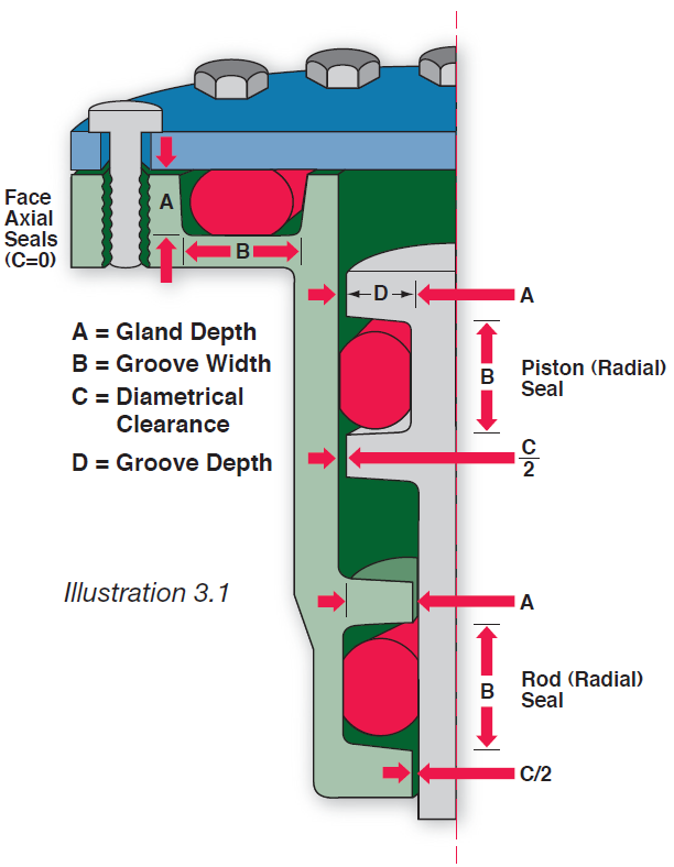
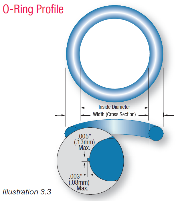
An O-ring is a doughnut-shaped object or torus. The opposite sides of an O-ring are squeezed between the walls of the cavity or “gland” into which the O-ring is installed. The resulting zero clearance within the gland provides an effective seal, blocking the flow of liquids or gases through the gland’s internal passage. An O-ring is defined by its dimensions (based on inside [hole] diameter and cross section), durometer (Shore A hardness), and material composition. Illustration 3.1 demonstrates three applications showing the two basic categories of O-rings: STATIC– contained within a non-moving gland as in a face seal, and DYNAMIC– contained within a moving gland as in a piston or rod seal.
Why an O-Ring Works
As Illustration 3.1 shows, a properly designed sealing system incorporates some degree of initial O-ring compression. At atmospheric pressure, only the resiliency of the compressed O-ring provides the seal. However, as system pressure activates the seal, the O-ring is forced to the low pressure side of the gland. Designed to deform, the O-ring “flows” to fill the diametrical clearance and blocks any further leakage. Illustration 5.1 in section 5 shows a progressive application of pressure and the effect it has on the seal. Pressure, as well as many other considerations, determine the effectiveness of a seal. These considerations are highlighted throughout this design guide.
Dimensional Considerations
Inside Diameter
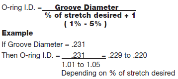
To provide an effective seal, the O-ring’s inside diameter (I.D.) must be smaller than the piston groove diameter, so that the O-ring is slightly stretched, fitting snugly in the groove. This stretch should be between 1%-5% with 2% as the ideal in most applications. A stretch greater than 5% is not recommended. The resulting stress on the O-ring will cause accelerated aging and cross section reduction. Exception to this rule is a floating seal. These are O-rings that are allowed to sit in grooves freely or “float”. These are used in applications where some leakage is allowed and less friction is required.
Common Applications
Calculate the O-ring I.D. according to the following formula:
Cross Section
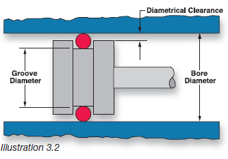
When calculating the cross section (C.S.) of an O-ring, you need to consider the size of the gland to be filled as well as the amount of squeeze needed to create a good seal. Virtually every gland has a slight gap between the two mating surfaces, termed “diametrical clearance.” Therefore, it is important for the O-ring cross-section to be greater than the gland height. The resulting O-ring
squeeze prevents leakage by blocking the diametrical gap.
Illustration 3.1 demonstrates that in “static” face seals or “dynamic” piston and rod seals, the O-ring is being squeezed slightly within the gland. Squeeze may occur in one of two possible ways. If the squeeze occurs on the top and bottom surfaces of the O-ring, as in face seals, it is referred to as AXIAL squeeze. If the squeeze is on the inner and outer surfaces of the O-ring, as in piston or rod seals, it is referred to as RADIAL squeeze.
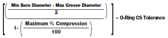
To obtain the correct amount of squeeze for optimum O-ring sealing, careful consideration must be given to the size of the O-ring in relation to the size of the glandular space into which the O-ring is being installed. The actual calculation for the cross section needed in an O-ring varies depending on whether it will be used in a dynamic or static application. In a dynamic situation, lower squeeze is recommended to reduce friction.
Dynamic (Moving) Radial Seal Cross Section Calculation
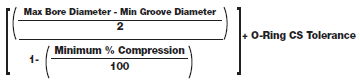
Referring to Illustration 3.2 for term definition, and Illustration 3.3 for sample dimensions, calculating the correct O-ring cross section for a specific gland depth is illustrated to the right. In the case of the dynamic piston seal shown, the cross section is calculated as follows:
Calculation of Maximum
O-Ring Cross Section:
- Enter the BORE DIAMETER
- Subtract the BORE tolerance from the BORE DIAMETER
- Enter the GROOVE diameter
- Add the GROOVE tolerance to the GROOVE diameter
- Subtract line 4 from line 2
- Divide line 5 by 2
- Enter the MAXIMUM % COMPRESSION
- Divide line 7 by 100
- Subtract line 8 from the number 1
- Divide line 6 by line 9
- Enter O-RING C.S. TOLERANCE
- Subtract line 11 from line 10 for the answer
Maximum
O-Ring CS =
Calculation of Minimum
O-Ring Cross Section:
- Enter the BORE DIAMETER
- Add the BORE tolerance to the BORE DIAMETER
- Enter the GROOVE DIAMETER
- Subtract the GROOVE tolerance from the GROOVE DIAMETER
- Subtract line 4 from line 2
- Divide line 5 by 2
- Enter the MINIMUM % COMPRESSION
- Divide line 7 by 100
- Subtract line 8 from the number 1
- Divide line 6 by line 9
- Enter O-RING C.S. TOLERANCE
- Add line 11 to line 10 for the answer
Minimum O-Ring
CS =
Static (Non-moving) Axial Seal Calculation
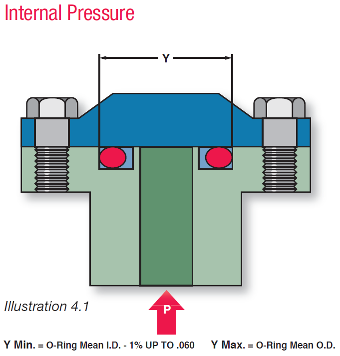
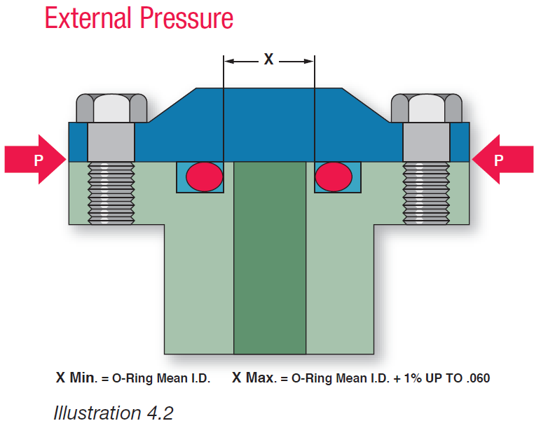
To calculate the cross section of an axial seal,determine the gland depth and then multiply by the maximum and minimum squeeze requirements, noting to add 1.00 to the recommended squeeze. For example, a recommended queeze of 30% would translate to a multiplied factor of 1.3. The O-ring I.D. is determined by the direction of pressure, whether from the I.D. or the O.D. If pressure forces the O-ring towards the inside, as shown in illustration 4.2, then the O-ring should be designed with the I.D. close to the groove I.D. However, if pressure forces the seal to the outside, as shown in illustration 4.1, then the seal should incorporate some interference on the O.D.
Material Considerations
After you have determined the O-ring size, you will then have to select the appropriate O-ring material.Listed in Section 6, “Material Selection Guide,” are various elastomers including statements of description, key uses, temperature ranges, features and limitations. Prior to seal purchase, make sure to take into account ALL of the factors discussed below. In addition, you might want to consider availability and cost. If a material is not shown.
Chemical Attack
A major consideration for O-ring material selection is resistance of specifi c elastomers to degradation by exposure to certain chemicals. Therefore, the first step in material selection is to match your application’s chemicals with the O-ring material that offers the best resistance. To do this, refer to the “Chemical Compatibility”
Temperature
The range of temperature experienced during operation is an important factor when consideringeffi cient sealing. It is particularly important to measure temperature in the immediate O-ring environment, not just the system temperature. You must also consider the length of exposure to any high temperature, whether it involves short bursts or long, sustained levels.
Friction
There are two types of friction, both of which are important considerations in dynamic (moving) applications. When part movement is intermittent,the effects of BREAKOUT FRICTION can cause excessively high pressures to develop. This pressure can tear portions of the seal that adhered to the gland wall causing seal failure.In continuously moving applications, excessive O-ring RUNNING FRICTION can cause heat to build up within the O-ring material itself. This causes swelling, which causes more heat to develop, and eventually results in seal extrusion and failure
Durometer
Durometer (Shore A) is a measurement of the hardness of an elastomeric compound. The numerical ratings for hardness run from lower numbered (less than 70) softer materials to higher numbered (greater than 70) harder materials, noting that fluorocarbon has a base rating of 75. This classification system is designed to work within a +/-5 point range. All materials are not available in all hardnesses.“Material Selection Guide,” for the range on individual
elastomers.
Pressure
The presence of high pressure on an O-ring can jeopardize its ability to seal. For correct O-ring design in high pressure situations, “Extrusion Limit” chart. However, low pressure can be a problem as well. If the system pressure is below 100 psi, it is classified as low pressure. Because system pressure is not great enough to “activate” the seal, the design must rely solely on the resiliency of the elastomer to retain its original compressive force. Over time, the elastomer will not resist compression as much and take a compression “set”, resulting in possible seal failure. However, by proper component design which may include lowering the seal durometer or increasing the cross section, maximum seal utility is achieved. For an illustration of this relationship
Flash
Flash is a thin, film-like material that extends beyond the parting line on the ID and OD of a molded part. Excessive flash is typically caused by mold separation or inadequate de-flashing.
Summary
For optimum sealing performance, correct O-ring selection is the direct result of a number of design considerations. These considerations include: size, squeeze, stretch, chemical compatibility, and the ability to resist pressure, temperature, and friction. ALL of these points of O-ring design are covered in detail within the sections of this Design Guide. For more information on any of these points, see the appropriate sections. Often, there are a number of materials that are appropriate for a particular application. Consideration should be given to the full range of environmental and cost factors. Your final selection will usually be a compromise in the sense that you have to balance all of these considerations.
|
Please Note the Following : The applications, suggestions and recommendations contained in this book are meant to be used as a professional guide only. Because no two situations or installations are the same, these comments, suggestions, and recommendations are necessarily general and should not be relied upon by any purchaser without independent verification based on the particular installation or use . We strongly recommend that the seal you select be rigorously tested in the actual application prior to production use. |
Seal Types & Gland Design
Major Classifi cations
All O-ring seal applications are categorized in terms of relative motion. In situations involving little or no motion relative to the seal, the O-ring application is STATIc. In situations involving reciprocating, rotating, or oscillating motion relative to the seal, the O-ring application is DYNAMIC.
Static Seal Types
Static seals are categorized as either AXIAL or RADIAL, depending upon the direction in which squeeze is applied to the O-ring’s cross section.
STATIC AXIAL SEALS
A static axial seal acts similar to a gasket in that it is squeezed on both the top and bottom of the O-ring’s cross section. This type of seal is typically employed in the face (fl ange) type applications, depicted in Illustration 4.1. When used as a face seal involving either internal or external pressure, the O-ring should always be seated against the low pressure side of the groove (as shown in Illustration 4.1 & Illustration 4.2) so the O-ring is already where it needs to be as a result of the pressure. Static axial seals tend to be easier to design than static radial seals. Since there is no extrusion gap, there are fewer design steps and you can control the tolerances easier.
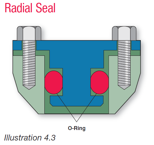
STATIC RADIAL SEALS
Static Radial Seals are squeezed between the inner and outer surfaces of the O-ring. They are typically employed in cap and plug type applications, as depicted in Illustration 4.3.
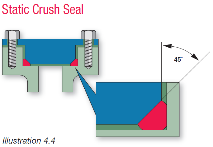
STATIC CRUSH SEALS
In crush seal applications, the O-ring is completely confi ned and pressure deformed (crushed) within a triangular gland made by machining a 45° angle on the male cover. Squeezed at an angle to the O-ring’s axis, crush seals are used in such simple applications as the one depicted in Illustration 4.4.
STATIC SEALS WITH DOVETAIL GLANDS
O-rings are sometimes employed in static or slow moving dynamic situations calling for specially machined “dovetail” glands. Because of the angles involved, controlling the tolerances in these glands may be diffi cult. The purpose of these glands is to securely hold the O-ring in place during machine operation and/or maintenance disassembly. A typical valve seat application is shown in Illustration 4.5.
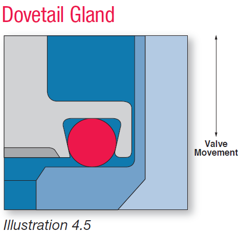
In this application, O-ring squeeze is primarily axial in direction (valve operation exerts force on top and bottom seal surfaces). To avoid tearing or nicking, the use of O-ring lubrication is recommended while installing the O-ring into the dovetail gland. Because of the diffi culty in creating the groove and tight tolerances required, this type of seal application should only be used when necessary.
Dynamic Seal Types
This classifi cation of seals is used in situations involving reciprocating, rotating or oscillating motion. Dynamic seal performance may be substantially affected by a number of operating environmental factors. Such factors include seal swell in fluids, surface finish of hardware components, lubrication, system pressure, thermal cycling, O-ring squeeze, O-ring stretch, and friction. Since many of these factors are interrelated, it is important to consider ALL of them in dynamic sealing situations.In discussions of individual dynamic seal types,therefore, mention will be made of the most critical operating environmental factors to consider. More detailed information on “critical Operating Environmental Factors”
Reciprocating Seals
RECIPROCATING SEAlS
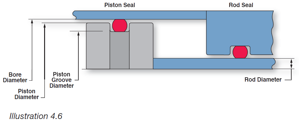
Reciprocating seals, as depicted in Illustration 4.6, are used in situations involving a moving piston and a rod. These seals constitute the predominant dynamic application for O-rings. For optimum performance of reciprocating seals, careful consideration of the following factors is required:
Compound Selection for Thermal Cycling:
Thermal cycling from high (100°F and above) to low (-65°F and below) temperatures may cause O-rings to take a compression set at elevated temperatures and fail to rebound enough at low temperatures to provide a leak-proof seal. Such O-ring leaks are especially prone to occur in low pressure, reciprocating applications. Therefore, when extreme operating thermal cycles are anticipated, it is recommended that you specify a seal compound that exceeds, rather than merely meets, desired temperature range, compression set, and resilience needs.
Control Over Pressure Shocks:
With sudden stopping and holding of heavy loads, hydraulic components can create system pressures far in excess of seal extrusion resistance capabilities. To prevent extrusion and eventual O-ring failure, pressure shocks should be anticipated and effectively dealt with in both seal selection and system design. As required, mechanical brakes or pressure relief valves may have to be built into the hydraulic system.
Stretch:
When the I.D. of an O-ring is stretched, the O-ring’s cross section is reduced. In such instances, be sure to consider that the O-ring’s reduced cross section maintains the correct percentage of seal squeeze. The percentage of stretch should not exceed 5% in most applications.

Rotary Seals
As shown in Illustration 4.7, O-rings may be used as seals for rotating shafts, with the turning shaft protruding through the I.D. of the O-ring.
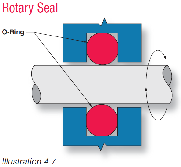
The most important factors to consider in designing rotary seal glands are application temperature limits, frictional heat buildup, O-ring stretch, squeeze, and shaft and glandular machining.
Application Temperature Limits:
Rotary shaft seals are not recommended for applications with operating temperatures lower than -40°F, or higher than +250°F. The closer the application is to room temperature, the longer the O-ring can be expected to effectively seal.
Frictional Heat Buildup:
As the generation of frictional heat is inevitable with rotary seal applications, it is suggested that O-rings be composed of compounds featuring maximum heat resistance and minimum friction generating properties. Internally lubricated compounds are typically used for rotary applications.
Stretch:
In this application, I.D. stretch must be eliminated by using shaft diameters no larger than the free state (relaxed) I.D. of the O-ring. Shaft seals for rotary or oscillating applications should be designed with no stretch over the shaft. When an elastomer is stressed in tension and the temperature is increased, it contracts instead of expands which increases the heat and additional contracting until seal failure. This contraction of an elastomer due to increased temperature is known as the Joule effect.
Squeeze:
In most rotational shaft applications, O-ring squeeze should be kept to as little as 0.002" by using an O-ring with an O.D. of about 5% larger than the accompanying gland. Once installed, peripheral compression puts the O-ring’s I.D. in light contact with the turning shaft. This design minimizes frictional heat buildup and prolongs seal life.
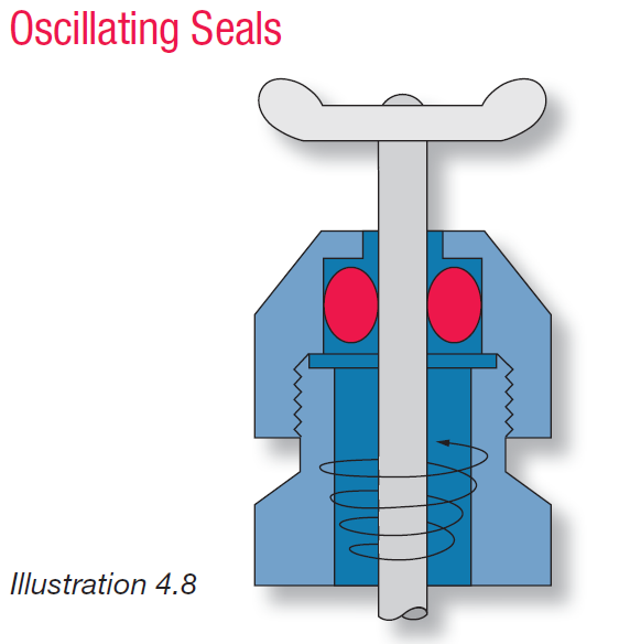
OSCILLATING SEAL
In an oscillating O-ring application, the shaft moves in an arc within the gland, and in contact with the I.D. of the seal. Because there is a tendency for the shaft to twist, self-lubricated O-rings with a hardness of 80 to 90 durometer are most often employed. caution should be used, however, with graphite-containing compounds as they tend to pit stainless steel alloys.
Oscillating Seal Gland Dimensions:
Oscillating seal gland dimensions are the same as those used for reciprocating applications
Machining
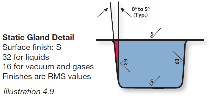
To preclude premature wear and seal failure, the metal surfaces which contact O-rings during installation and system operation must be properly prepared. Preparation consists of appropriate selection of materials, as well as machining for optimum surface finish. To prevent O-ring extrusion or nibbling, rectangular, straight-sided, glandular grooves are best. For pressures up to 1,500 psi, 5° sloping sides are acceptable and easier to machine. Break all sharp corners by at least 0.005" to avoid unnecessary cutting or nicking of O-rings during assembly and operation.
Surface Finishes
STATIC GLANDS
Surface fi nishes as rough as 64 to 128 micro-inches RMS can be tolerated. however, a fi nish of 32 microinches RMS is preferred.
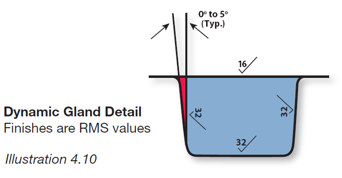
DYNAMIC GLANDS
Reciprocating Seals
A highly polished surface is not desirable because it will not hold lubricant. The most desirable metal surface roughness value for dynamic seal applications is from 10 to 20 micro-inches. A shot-peened or electro-polished surface is ideal, because it provides many small pockets in the metal for entrapment of lubricants. The best surfaces are honed, burnished or hard chrome plated. Softer metallic surfaces, such as aluminum or brass, should generally not be used for dynamic applications.
Rotary Seals
Shaft composition should be of a relatively hard metal and be within 0.0005" TIR. Additionally, it is recommended that shaft surfaces be fi nished to 16 RMS (for smooth, non-abrasive running), with gland surfaces fi nished to a rougher 32 RMS (to discourage O-ring movement within the gland).
O-Ring Installation
An O-ring may be easily damaged by improper handling and may fail for this reason alone. Prior to O-ring installation, make sure that ALL glandular surfaces are free of all debris. If necessary, clean these surfaces with an appropriate solvent THAT IS COMPATIBLE WITH THE O-RING BEING INSTALLED.
Before installation, make sure to lightly coat the O-ring with a lubricant that is compatible with the O-ring being installed, as well as compatible with system chemicals.
In piston applications, avoid stretching the O-ring more than 100% during installation (stretch should not exceed 5% in the application). Also, be sure to stretch it uniformly. Cones, or mandrels, are often used to assist in these installations. Once the O-ring has been installed, make certain to remove any twists.
When the piston is pushed into the cylinder, push it straight in. DO NOT TURN OR TWIST PISTONS INTO CYLINDERS AS THIS MAY BUNCH OR CUT O-RINGS!
In installations where the O-ring must pass over threads or other sharp edges, cover these edges with tape or a plastic thimble prior to O-ring installation.
As necessary, O-rings may be folded into internal grooves, but excessive twisting should again be avoided.
In hydraulic systems, it is recommended that glandular surfaces be washed with hydraulic fluid, then cleaned with a LINT-FREE cloth.
In all cases of O-ring installation, try to avoid excessive twisting, turning, rotating, or oscillating of glandular components relative to the O-ring. Also try to avoid O-ring contact with any sharp surfaces, including fingernails.
Note: The tables that follow represent a compilation
of data from various sources to aid in the design of an
effective seal. Because each sealing application
is unique, the presented data should be
referred to as a proper initial step, with more
specific design criteria on the following www.ecosealthailand.com
Critical Operating Environmental Factors
Chemical Compatibility
Regardless of all other critical design factors, if the basic composition of the O-ring material is not compatible with its chemical environment, the O-ring will eventually fail.A primary step in O-ring selection, therefore, is to match yourapplication’s chemicals with the O-ring material that offers the best chemical resistance. To do this
The Effect of Pressure
Differential pressure affects an O-ring by forcing it to the low pressure side of the gland, causing the cross section to distort (See Illustration 5.1).
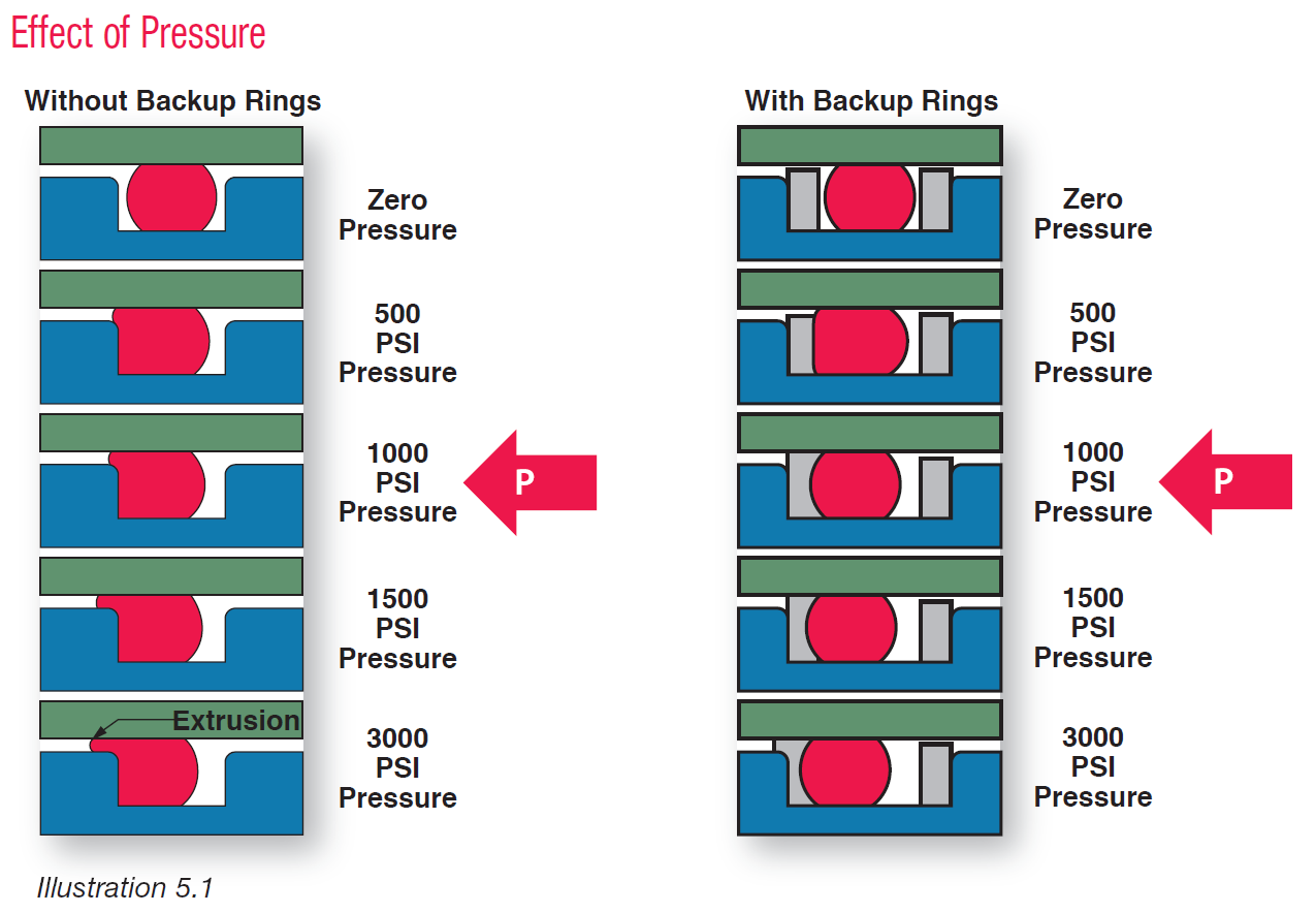
This motion blocks the diametrical clearance gap between the mating surfaces and forms the seal. If the O-ring cannot resist increasingly high pressure, part of the O-ring will be forced (extruded) into the diametrical gap. This condition leads to premature failure, leakage and system contamination. O-rings operate optimally within a certain range of pressure. Differential pressure does aid in sealing potential by compensating for the elastomer’s tendency to assume a compression set over time, which reduces O-ring compression and utility.
Methods commonly used to prevent O-ring extrusion under pressure include:
- increasing the O-ring hardness (durometer)(See Illustration 5.2)
- the use of back-up rings to block the diametrical clearance gap and provide support for the O-ring
- reducing the diametrical clearance gap dimension
- lowering of system pressure
Use of Back-Up Rings
As shown in Illustration 5.2, the extrusion limit of O-rings under pressure is determined by the size of the diametrical clearance gap and the hardness of the O-ring material. If the point representing the intersection of the lines of sealed pressure and diametrical clearance falls to the right of the material’s hardness curve, either the material hardness must be increased, or the diametrical clearance reduced; otherwise, back-up rings will be required.
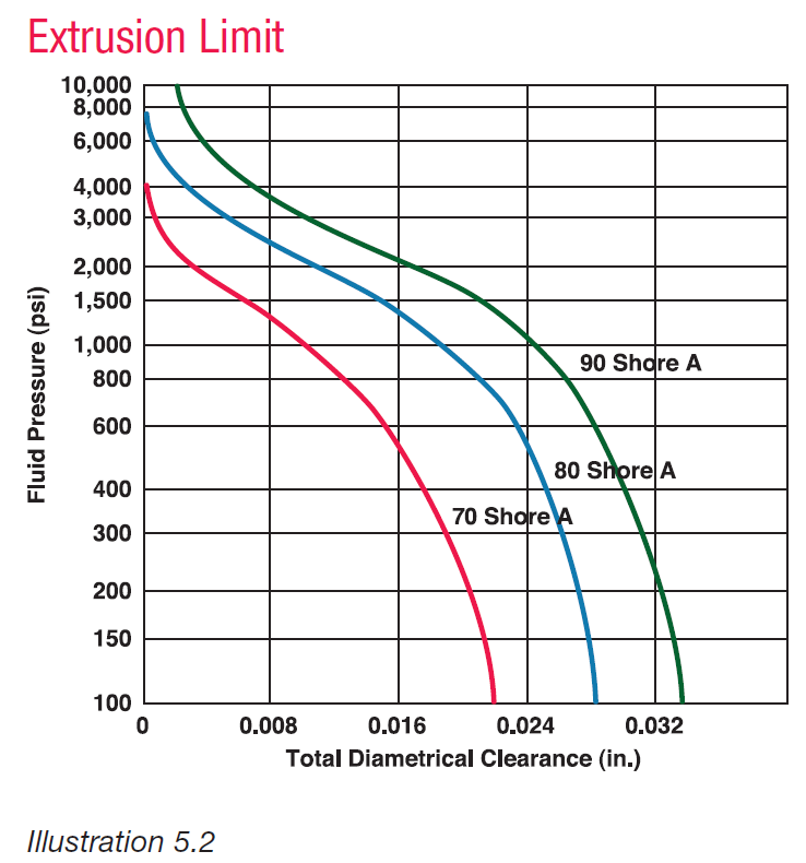
Examples
A. Material hardness of 70 Shore A. Sealed pressure of 1,000 psi. Diametrical clearance of .016". Intersection of sealed pressure and diametrical clearance lines falls to the right of material hardness curve. Increase hardness, use back-up rings, or reduce diametrical clearance.
B. Material hardness of 80 Shore A. Sealed pressure of 1,000 psi. Diametrical clearance of .016". Intersection of sealed pressure and diametrical clearance lines falls to the left of material hardness curve. This is acceptable. The use of two back-up rings (one on each side of the rings) is preferred. This will help prevent installation errors, assuring that the clearance gap is always correctly blocked, regardless of pressure direction.
Seal Compression (Squeeze)
O-ring compression is a result of three factors: the force applied to compress the seal, durometer, and cross section. These relationships are demonstrated in Illustration 5.3. Additionally, O-ring stretch affects seal compression by reducing cross section, which reduces the sealing potential of the O-ring. This relationship is demonstrated in the equation below.
O-ring CS Reduced Due to Stretch (calculated)
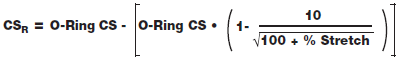
The calculated value assumes the O-ring volume does not change and the cross-section remains round when stretched.
Illustration 5.3 is comprised of a great deal of information regarding O-ring compression. Within the body of the graph are the various durometers for standard cross sections. Nonstandard cross sections and omitted durometers can be inferred from the generally linear relationship between the amount of applied compressive force and seal compression, durometer and cross section.

The Effects of Friction
BREAKOUT FRICTION is an important consideration in intermittently moving applications. It can cause excessively high hydraulic pressures to develop. This pressure can tear portions of the seal that adhere to the gland wall when machine movement has been stopped for an extended period of time. Once a system is up and running, the designer must then consider seal RUNNING FRICTION as a potential source of problems. In continuously moving applications, excessive running friction can cause heat to develop, which results in O-ring swell. Once swelling occurs, more heat is generated from increased friction which causes additional swelling and seal failure. High running friction, in combination with high system pressures, may also produce excessive wear in soft metal parts.
Methods Used to Control Friction
Squeeze: Both running and breakout friction are reduced when squeeze is reduced.
Durometer (Hardness): Breakout friction decreases with DECREASING hardness. Running friction decreases with INCREASING hardness.
Cross Section: O-rings with smaller cross sections tend to produce less friction.
Lubrication: Seal adhesion can be minimized by the use of lubrication. Compatibility between the elastomer and lubricant should be predetermined to avoid seal shrinkage or swelling.
Compound Additives: Rubber can be compounded with additives such as oils, graphite, Teflon®, etc. to lower the coefficient of friction.
Gland Machining: An optimum finished surface of 8 to 16 RMS will help control friction. Finishes below 5 RMS will not hold the lubricant because it eliminates micropores.
Groove Width: By increasing the groove width, the seal will be allowed more room to expand perpendicular to the compressive force.
Material: Materials vary in their friction and wear properties. For example, Teflon® has a very low coefficient of friction. For more complete information on individual materials see Section 6.
Pressure: Decrease system pressure to reduce the amount of running friction.
The Effect of Temperature
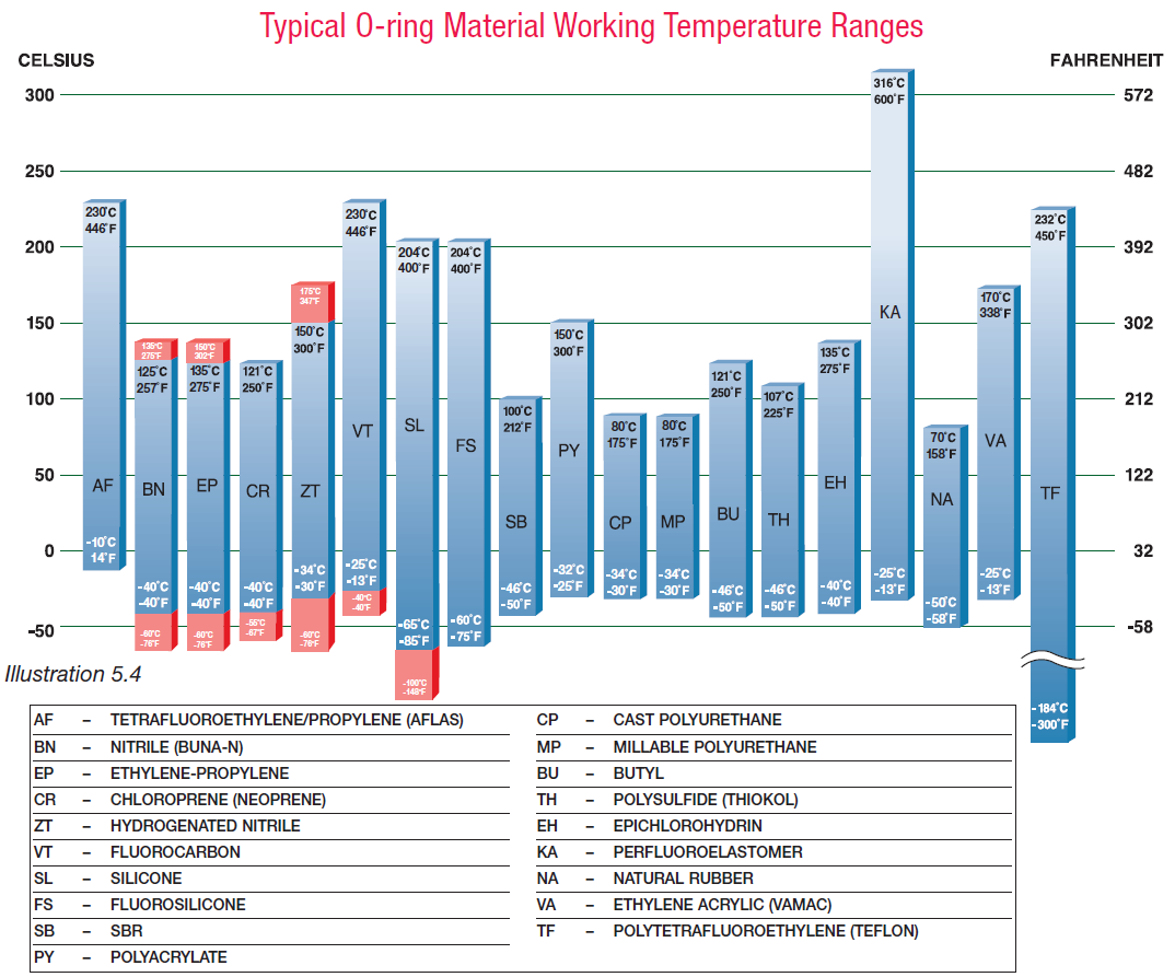
Over time, excessive heat degrades O-ring materials physically and/or chemically, which may render them non-functional. Excessive heat is known to cause O-ring materials to both swell and harden, taking a permanent compression set (deformation of shape) within the gland. Cold temperatures, without proper material selection to resist the effect of extreme cold, results in O-ring shrinkage and possible leakage due to a reduction in surface contact. Extreme cold also affects O-rings by making them brittle and less fl exible. For optimum sealing performance, always attempt to keep the O-ring application within the temperature ranges listed on the individual material data sheets shown in ion 6, “Material Selection Guide.” For quick reference, typical O-ring material working temperature ranges are as shown in Illustration 5.4.
This chart refers to the range of temperatures for families of compounds. A specifi c compound may not have the full temperature range shown. The red bar graph section designates the range provided by special compounds.
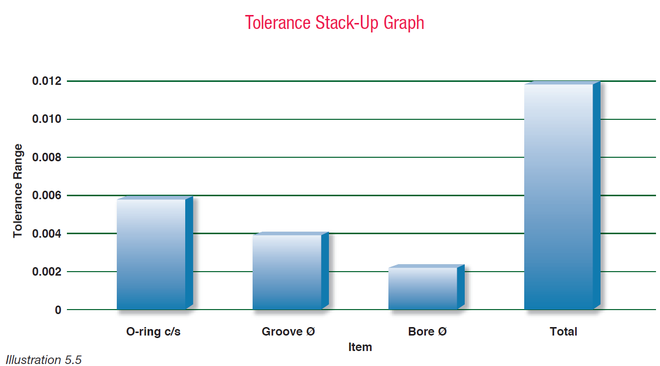
Tolerance Stack-Up
In any sealing application, the tolerances of ALL the parts in contact with the O-ring must be considered in order to create an effective seal. The combination of these tolerances is the tolerance stack-up. Illustration 5.5 shows a situation where the O-ring cross section tolerance is ± 0.003", the groove diameter tolerance is ± 0.002", and the bore diameter tolerance is ± 0.001". In this example the metal and O-ring dimensions can vary up to 0.012". If the nominal O-ring size is 0.030", it is easy to see that the tolerance stack-up is nearly half the size of the O-ring. This can result in too much or too little compression which can cause the O-ring to fail.
<
Material Selection Guide
Basic Concepts of Rubber
What is “Rubber”?
“Rubber” refers to elastomeric compounds that consist of various monomer units forming polymers that are heat cured (vulcanized). Polymers are long molecular chains and are derived from the Greek “poly” (many) and “meros” parts). The base monomer or monomers is used to classify the type of rubber, for example: Nitrile, Silicone or Neoprene.
What is a Rubber Compound?
Rubber is composed of many different ingredients that include the base elastomer, vulcanization agents, fillers and plasticizers. For example, the addition of fillers can reinforce or modify properties, or additional plasticizer can increase elongation and lower durometer.
Why Does Rubber Act “Rubbery”?
Rubber is considered highly viscous liquid or an elastic solid. The polymeric chains in rubber tend to be very long and flexible by nature and can rotate about their axis, which results in an entangled mass of contorted chains. When a deformation of the rubber occurs, these tangled chains uncoil and recoil when the force is released. Therefore, elastic rebound or rubbery behavior is possible due to contortions of long, flexible polymeric chains, which allow rubber to be so resilient.
How is Rubber Made?
The base polymer is the primary component of all rubber recipes and is selected in order to obtain specific chemical and physical properties in the final product. Processing aids and softeners, such as oils and plasticizers, modify rubber to aid in mixing or molding operations. Sulfur is one of the most widely used vulcanizing agents to promote crosslinking which is used in conjunction with accelerators and accelerator activators to reduce cure times and enhance physical properties. Carbon black is one of the most common fillers because it reinforces the molecular structure. Antidegradants, such as antioxidants and antiozonants, retard the deterioration of rubber products. Lubricants, colors or any other miscellaneous ingredients may also be added.
What is Vulcanization?
The long, flexible polymeric chains of rubber, when heated, react with vulcanizing agents to form three-dimensional structures. These vulcanizing agents (usually sulfur or peroxide) are necessary to facilitate chemical crosslinking of polymeric chains. Once the rubber has been vulcanized or “cured”, physical properties are enhanced and the compound is more resistant to deterioration.
What is Compression Set?
Elastic recovery is a measure of the elastomer’s ability to return to its original shape once a compressive force has been removed. Failure of the seal to return to its original shape after compression is the condition termed “compression set” and all seals exhibit some degree of compression set. Determination of the amount of compression set is governed by ASTM designation D395 test procedure.
What is the difference between a Thermoset and Thermoplastic?
One classification method of polymeric materials is according to physical properties at elevated temperatures. Thermoset polymers become permanently “set” in the presence of heat and do not soften in the presence of subsequent heating. Conversely, a thermoplastic material will soften when heated (and eventually liquefy) and harden when cooled. This process is reversible and repeatable, as opposed to thermoset polymers where the process is irreversible. Also, thermoset polymers possess superior mechanical, thermal, and chemical properties as well as better dimensional stability than thermoplastic elastomers. This is why thermoset (rubber) parts are generally preferred for sealing applications. This section contains descriptions of the elastomers used in seal applications. These elastomers form the base of a wide variety of compounds, designated forspecific applications. Every compound has specific characteristics and many compounds have common attributes. Therefore, it is important to consider all aspects of the compound prior to use. Also, as compound availability is customer driven, lead time may vary.
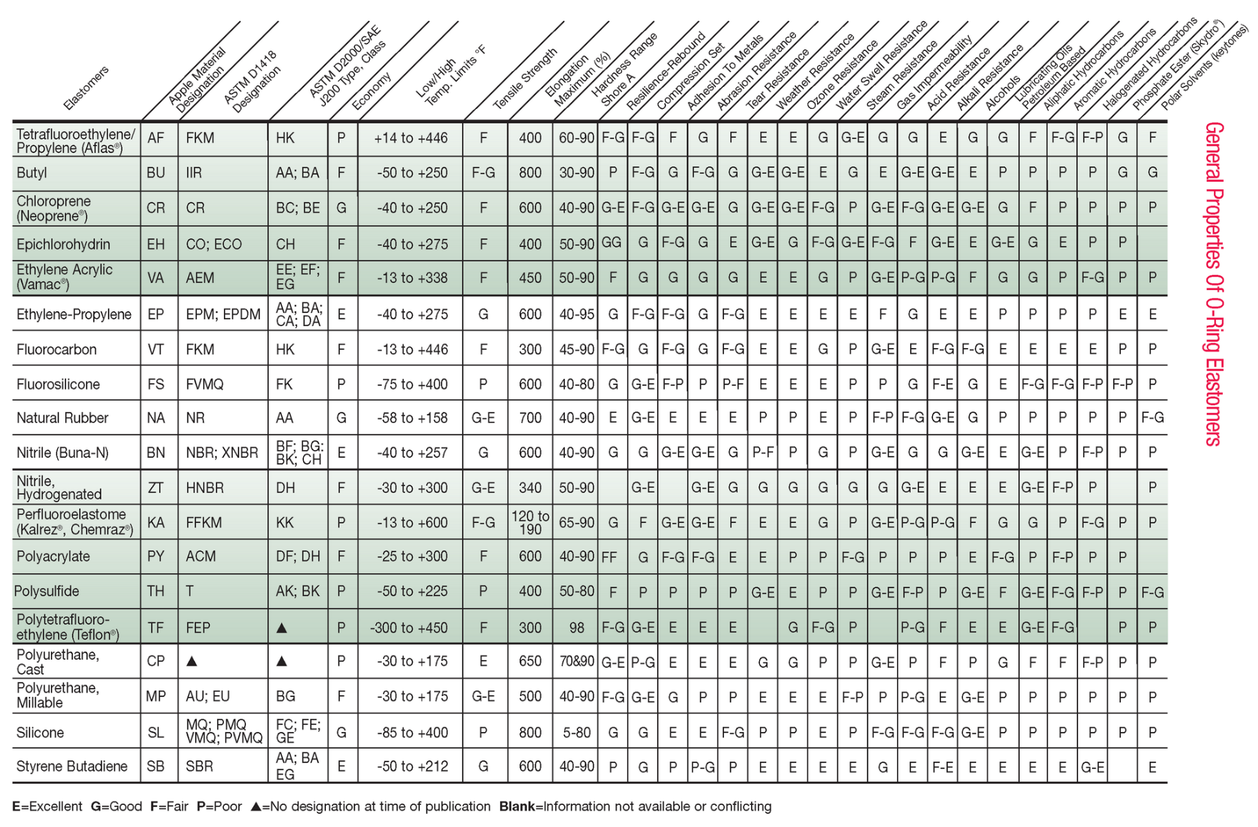
Chemical Compatibility Table
Butyl
Trade Name(s):
Exxon Butyl ... Exxon Chemical
Polysar Butyl ... Bayer Polymer
Standard Color: Black
Description: An all-petroleum product, Butyl is a copolymer of isobutylene and isoprene and has largely been replaced by Ethylene Propylene since its introduction.
Key Use(s): Highly effective in vacuum sealing applications. Good seal for hydraulic systems.
Temperature Range: Standard Compound: -50°F to +250°F.
Hardness (Shore A): 30 to 90
Features: With outstanding low permeability to gases, Butyl is especially effective in vacuum sealing applications. It also features good to excellent resistance to ozone and sunlight aging. Butyl further features excellent shock dampening capabilities. Only slightly affected by oxygenated solvents and other polar liquids, Butyl is often utilized in seals for hydraulic systems using synthetic fluids. It is good with MEK, and silicone fluids and greases.
Limitations: Because it is a petroleum product, Butyl has poor resistance to hydrocarbon solvents and oils, and diester-based lubricants. Halogenated butyl has been introduced to expand oil and chemical resistance to this polymer. Chlorobutyl and Bromobutyl have better resistance. These polymers have been accepted by the medical industry for stoppers and septumns for pharmaceutical applications.
Fluorocarbon (Viton®)
Trade Name(s):
Viton® ... DuPont Performance Elastomers
Fluorel ... 3M Company
Technoflon ... Solvey Solexis, USA
Standard Color: Black
Description: Combining high temperature resistance with outstanding chemical resistance, Fluorocarbonbased compounds approach the ideal for a universal O-ring material.
Key Use(s): Seals for aircraft engines. Seals for automotive fuel handling systems. High temperature/ low compression set applications. Wide chemical exposure situations. Hard vacuum service.
Temperature Range: Standard Compound: -13°F to +446°F. Special Compounds: -40°F to +446°F.
Hardness (Shore A): 45 to 90.
Features: High fluorine grades offer higher resistance to swell in high octane and oxygenated fuel blends. This gives superior performance in Ethanol/Methanol blended gasoline. Base resistant grades offer improved resistance to amine based oil protectants found in new transmission oils. Also, improved resistant to steam for higher temperature services. Low temperature bases can improve performance to -40°F. New polymers being offered have improved chemical resistance and low temperature performance. Viton® Extreme™ ETP offers similar chemical compatibility as Kalrez™ with temperature resistance to +446°F. Special compounds, using new polymer technologies, provide improved low temperature performance with a TR(10) of -40°F and brittleness to -76°F. Limitations: Fluorocarbons are not recommended for exposure to ketones, amines, low molecular weight esters and ethers, nitro hydrocarbons, hot hydrofluoric or chlorosulfonic acids, or Skydrol® fluids. They are also not recommended for situations requiring good low temperature flexibility.
Fluorosilicone
Trade Name(s):
Silastic LS ... Dow Corning Corporation
FSE ... Momentive Performance Materials
Standard Color: Blue
Description: Fluorosilicone combines the good high and low temperature stability of Silicones with the fuel, oil, and solvent resistance of Fluorocarbons. Key Use(s): Aerospace fuel systems. Auto fuel emission control systems. Primarily for static sealing applications.
Temperature Range: Standard Compound:-75°F to +400°F.
Hardness (Shore A): 40 to 80.
Features: Fluorosilicone is most often used in aerospace applications for systems requiring fuel and/ or diester-based lubricant resistance up to 400°F. Although generally specified for aerospace use, due to its excellent fuel resistance and high temperature stability, Fluorosilicone is becoming an increasingly popular material for a wider range of sealing applications. Featuring good compression set and resilience properties, fluorosilicone compounds are suitable for exposure to air, sunlight, ozone, chlorinated and aromatic hydrocarbons. Limitations: Due to limited physical strength, poor abrasion resistance, and high friction characteristics, Fluorosilicone elastomers are not generally recommended for dynamic sealing. They are predominately designed for static sealing use. They are also not recommended for exposure to brake fluids, hydrazine, or ketones.
Liquid Silicone Rubber (LSR)
LSR is a low viscosity silicone elastomer intended for use in liquid injection molding (LIM) equipment. It offers high thermal stability and flexibility at low temperatures, high transparency and is easily colored. Also, self-lubricated and electrically conductive grades are available as well as FDA and medical compliant grades. Liquid silicone rubber is widely used to mold complex profiles because of its excellent flow characteristics.
Medical Grade Silicone
When properly prepared, possible benefits include fulfillment of USP Class VI and ISO 10993 requirements, embrittlement from gamma sterilization, sterilizable with EtO/steam. Also, this grade of silicone is generally transparent due to class requirements. Limited medical grade pigments are available. Limitations: Generally, low abrasion and tear resistance, and high friction characteristics preclude silicones from effectively sealing some dynamic applications. Silicones are also highly permeable to gases and are generally not recommended for exposure to ketones (MEK, acetone) or concentrated acids.
Natural Rubber
Standard Color: Black
Description: Natural Rubber is the vulcanized product of the juice of the Hevea tree (latex).
Key Use(s): Seals in food and beverage applications. Most popular material for non-hydraulic sealing applications. Mainly used for dampeners due to its ability to absorb vibration.
Temperature Range:Standard Compound: -58°F to +158°F. (Dry Heat Only)
Hardness (Shore A): 40 to 90.
Features: Natural Rubber features high tensile strength, high resilience, high abrasion and high tear resistance properties, with a good friction surface and excellent adhesion to metals. Until the invention of synthetic elastomers in the 1930’s, Natural Rubber was the only polymer available for O-ring manufacture. Natural Rubber features good resistance to organic acids and alcohols, with moderate resistance to aldehydes.
Limitations: Not widely used in sealing industry due to poor compression set performance and lack of resistance to many fluids.
Nitrile (Buna-N)
Trade Name(s):
Nipol ... Zeon Krynac ... Bayer Polymer
Nysyn ... DSM Elastomers Chemigum ... Eliokem
Standard Color: Black
Description: Presently, the seal industry’s most widely used and economical elastomer, Nitrile combines excellent resistance to petroleum-based oils and fuels, silicone greases, hydraulic fluids, water and alcohols, with a good balance of such desirable working properties as low compression set, high tensile strength, and high abrasion resistance. Use of Carboxylated Nitrile can have superior abrasion resistance, while still having improved oil resistance.
Key Use(s): Oil resistant applications of all types Low temperature military uses. Off-road equipment. Automotive, marine, aircraft fuel systems. Can be compounded for FDA applications.
Temperature Range: Standard Compound: -40°F to +257°F. Special Compounds: -67°F to +275°F. (Dry Heat Only)
Hardness: (Shore A): 40 to 90.
Features: Comprised of the copolymer butadiene and acrylonitrile, in varying proportions. Use of Carboxylated Nitrile can have superior abrasion resistance, while still having improved oil resistance.
Limitations: Nitrile compounds are attacked by small amounts of Ozone. Phthalate type plasticizers are commonly used in compunding Nitrile rubber. These plasticizers can migrate out and cause problems with certain plastics. Also,new regulation on certain phthalates have limited their use.
Nitrile, Hydrogenated (HNBR)
Trade Name(s):
Zetpol ... Zeon Co., Ltd.
Therban ... Bayer
Standard Color: Black
Description: HNBR is the product of the hydrogenation of Nitrile, resulting in varying degrees of saturation of the polymeric chain, along with a range of enhanced physical strength and chemical resistance properties.
Key Use(s): ALL oil resistant applications, including exposure to such oil additives as detergents, anti-oxidants and anti-wear agents. Exposure to oil soured with metal sludge. Seals for oil well applications. Seals for automotive fuel handling systems. Seals for general industrial usage.
Temperature Range: Standard Compound: -30°F to +300°F. (Dry Heat Only) Special Compounds: -76°F to +347°F.
Hardness (Shore A): 50 to 90
Features: Like Nitrile, increasing acrylonitrile content improves oil resistance at a cost of reduced low temperature performance.
Limitations: Like Nitrile, HNBR is not recommended for exposure to ethers, esters, ketones, or chlorinated hydrocarbons.
Perfluoroelastomer
Trade Name(s):
Chemraz® ... Green, Tweed & Co.
Kalrez® ... DuPont Performance Elastomers
Tecnoflon PFR ... Solvay Solexis
Standard Color: Black
Description: FFKM parts are made from a perfluoroelastomer possessing exceptional resistance to degradation by aggressive fluids and/or gases.
Key Use(s): Seals for use in the chemical and petroleum industries as well as for the manufacturing of semiconductors and analytical and process instruments. It is also used for high temperature applications and for paint and coating operations.
Temperature Range:Standard Compound: -13°F to +600°F.
Hardness (Shore A): 65 to 90
Features: FFKM combines the toughness of an elastomeric material with the chemical inertness of Teflon®. It resists attack by nearly all chemical reagents and provides long-term service where corrosive additives can cause other elastomers to swell or degrade. In addition, FFKM parts are less likely to cold flow than Teflon seals.
Limitations: Withstanding degradation by virtually ALL chemicals, FFKM can swell significantly when exposed to some fluorinated solvents, fully halogenated freons and uranium hexafluoride. In addition, FFKM parts should not be exposed to molten or gaseous alkali metals. As the thermal coefficient of expansion for FFKM is stated by the manufacturer to be “about 50% greater than for fluoroelastomers”, gland volume may have to be increased to allow for this expansion in elevated temperature situations. Because of its high cost, FFKM is generally used when no other elastomer is appropriate.
Polyacrylate
Trade Name(s):
HyTemp ACM ... Zeon
Acralen A ... Bayer Polymer
Standard Color: Black
Description: Polyacrylates are copolymers (ethyl acrylates) possessing outstanding resistance to petroleum fuels and oils.
Key Use(s): Sealing automatic transmissions & power steering systems. Sealing petroleum oils up to 300°F.
Temperature Range: Standard Compound: -25°F to +300°F.
Hardness (Shore A): 40 to 90.
Features: With excellent resistance to hot oil, automatic transmission and Type A power steering fluids, the greatest use for Polyacrylate is found in automobile manufacture, where O-rings of this material are employed to seal components of automatic transmission and power steering systems. Highly resistant to sunlight and ozone degradation, Polyacrylate also features an enhanced ability to resist flex cracking.
Limitations: While resistance to hot air aging is superior to Nitrile, Polyacrylate strength, compression set, water resistance properties and low temperature capabilities are inferior to many other polymers. Polyacrylates are also not generally recommended for exposure to alcohol, glycols, alkalis, brake fluids, or to chlorinated or aromatic hydrocarbons.
Polysulfide
Trade Name(s):
Thiokol® (types A, B, FA, ST) ... Thiokol Corp.
Standard Color: Black
Description: Another of the early developed synthetic elastomers, Polysulfide offers a remarkable combination of solvent resistance, low temperature flexibility, flex crack resistance, oxygen and ozone resistance, and gas impermeability.
Key Use(s): Seals for paint and coatings and insecticide industry use.
Temperature Range: Standard Compound: -50°F to +225°F.
Hardness (Shore A): 50 to 80
Features: Resistant to a wide range of solvents, including ketones, ethers, and aromatic hydrocarbons. Polysulfide has gained wide acceptance as a seal material for paints and coatings, and insecticides.
Limitations: With poor heat resistance, poor mechanical strength and compression set properties, Polysulfides are not as versatile as other elastomers from a performance standpoint. They are also not recommended for exposure to mercaptans, esters, amines, chlorinated or nitro hydrocarbons.
Polytetrafluoroethyne (Teflon®)
Trade Name(s):
Teflon® ... DuPont Dow Elastomers
TFM ... Dyneon
Standard Color: White
Description: Teflon® is a tough, chemically inert polymer possessing an incredible working temperature range.
Key Use(s): Seals for wide chemical exposure situations, with special emphasis on temperature extremes. For static and SLOW INTERMITTENT dynamic situations.
Temperature Range: Standard Compound: -300°F to +450°F.
Hardness (Shore A): 98.
Features: Teflon® is inert to virtually all industrial chemicals, even at elevated temperatures. Seals fabricated from this material feature outstanding weather resistance, high resistance to ozone, and high resistance to the degrading effects of exposure to such solvents as acetone, MEK, and xylene. Possessing average elastomer characteristics of 2,500 to 3,500 psi tensile strength, and 300% elongation, they are tough, impact resistant, low friction, non-twisting performers over an extremely wide temperature range.
Limitations: Teflon® is hampered by very poor elastic memory at room, or low temperatures. This presents problems in O-ring installation, requiring extra care to be taken in control over O-ring I.D. stretch. Heating Teflon® in boiling water, or in a controlled oven, to 200°F is said to enable an O-ring stretch of 10 to 20% to be achieved, thereby assisting installation, and helping to assure a tight fit. Because of its poor tear resistance, during O-ring installation particular care should be taken to avoid nicking or scratching Teflon®, as imperfections will cause O-ring leakage. Finally, the tendency of virgin Teflon® to cold flow over time, when used in gasket type applications, may require special material compounding (with fillers) to control such “creep” in critical sealing situations.
Polyurethane, Cast
Trade Name(s):
Vibrathane ... Uniroyal
Cyanaprene ... American Cyanamid
Polathane ... Polaroid
Standard Color: Amber
Description: Cast Polyurethane is outstanding over other O-ring elastomers in abrasion resistance and tensile strength. Additionally, Cast Polyurethane surpasses the performance of Millable Polyurethane in its higher tensile strength, greater elongation, wider temperature range, and lower compression set characteristics.
Key Use(s): Seals for high hydraulic pressures. Situations where highly stressed parts are subject to wear. Used for wheels, rolls, slurry parts, bumpers, couplers, and shock absorbers. Wiper seals for axially moving piston rods.
Temperature Range: Standard Compound:-30°F to +175°F.
Hardness (Shore A): 70 and 90.
Features: With tensile strength of up to 6,000 psi, elongation of 350 to 650%, compression sets of 10 to 25%, and exceedingly high abrasion resistance, the physical properties of Cast Polyurethane are among the best of all O-ring elastomers. Although they swell slightly upon exposure, Cast Polyurethane compounds feature excellent resistance to mineral-based oils and petroleum products, aliphatic solvents, alcohols and ether. They are also compatible with hydraulic fluids, weak acids and bases, and mixtures containing less than 80% aromatic constituents.
Limitations: Cast Polyurethanes are not recommended for exposure to concentrated acids and bases, ketones, esters, very strong oxidizing agents, pure aromatic compounds and brake fluids. With the exception of special compounds, they are also not recommended for exposure to hot water or steam.
Polyurethane, Millable
Trade Name(s):
Millathane® ... TSE Industries Inc.
Standard Color: Black
Description: Millable Polyurethane is outstanding over most other O-ring elastomers in abrasion resistance and tensile strength.
Key Use(s): Seals for high hydraulic pressures. Situations where highly stressed parts are subject to wear.
Temperature Range: Standard Compound: -30°F to +175°F.
Hardness (Shore A): 40 to 90
Features: Millable Polyurethane offers superior seal performance in hydraulic situations, where high pressures, shock loads, or abrasive contamination is anticipated. Millable Polyurethane possesses chemical compatibility similar to that of Nitrile, offering good resistance to petroleum-based oils, hydrocarbon fuels and hydraulic fluids, the oxidizing effects of ozone, and the aging effects of sunlight. It also has good tear resistance.
Limitations: Unless specially compounded, at elevated temperatures Millable Polyurethane begins to soften, losing its physical strength and chemical resistance advantages over other polymers. Tending to rapidly deteriorate when exposed to concentrated acids, ketones, esters, chlorinated and nitro hydrocarbons, Millable Polyurethanes are also prone to hot water and steam degradation.
Silicone
Trade Name(s):
Elastosil ... Wacher
Silastic ... Dow Corning
Silplus ... Momentive Performance Materials
Standard Color: Red
Description: A group of elastomers, made from silicon, oxygen, hydrogen and carbon, Silicones are renowned for their retention of flexibility and low compression set characteristics, within one of the widest working temperature ranges for elastomers.
Key Use(s): Static seals in extreme temperature situations. Seals for medical devices, compatible with FDA regulations.
Temperature Range: Standard Compound: -85°F to +400°F. Special Compounds: -148°F to +400°F.
Hardness (Shore A): 5 to 80
Features: Phenyl (PVMQ) based silicones can perform to -148°F. New polymers can take short term to 600°F
Styrene Butadiene
Trade Name(s):
Too numerous to list.
Standard Color: Black
Description: Also known as Buna S, or GR-S (Government Rubber-Styrene), Styrene Butadiene was the elastomer substituted for Natural Rubber during World War II. Compounded properties are similar to those of Natural Rubber.
Key Use(s): Isolation dampeners.
Temperature Range: Standard Compound:-50°F to +212°F. (Dry Heat Only)
Hardness (Shore A): 40 to 90.
Features: The main use for Styrene Butadiene today is in the manufacture of automobile tires.
Limitations: SBR is not recommended for exposure to petroleum oils, most hydrocarbons, strong acids, or ozone.This material is seldom used in modern sealing applications. It has been replaced by better performing materials.
Tetrafluoroethylene/Propylene (Aflas®)
Trade Name(s):
Aflas® ... Asahi Glass Co., Ltd.
TBR ... Dupont Performance Elastomers
Standard Color: Black
Description: A copolymer of tetrafluoroethylene/ propylene, TFE/P can offer a combination of high temperature and chemical resistance.
Key Use(s): Seals for oil field, aerospace, chemical and general industrial environments. Temperature Range: Standard Compound: +14°F to +446°F.
Hardness (Shore A): 60 to 90.
Features: Resistance to a wide range of chemicals, high temperature and electrical capabilities give broad application diversity. TFE/P have resistance to acids and bases, steam/hot water, corrosion inhibitors, oils and lubricants, and industrial solvents. TFE/P also offer improved low temperature properties over most fluoroelastomers.
Limitations: Tests have shown that other FKM elastomers are recommended for automotive fuels since they have less volume swell than TFE/P. Also, TFE/P has shown to have less than desirable results when exposed to toluene, thers, ketones, and acetic acid.
Thermoplastic Elastomers
Description: Thermoplastic elastomers combine the processing advantages of plastics with the rubberlike performance of elastomers. Known as two-phase systems, these copolymers are comprised of both hard (plastic) and soft (elastomeric) molecular regions, with each region contributing advantages and limitations to the final material performance. Chemically, fully-cured thermoset rubber particles are dispersed throughout a continuous thermoplastic matrix. Examples of this class of material are Santoprene® and Geolast® from Advanced Elastomer System (AES) and Dynaflex™ from GLS Corporation.
Key Use(s): A broad range of applications that spans from bumpers to bellows, vibrational dampers, couplers, and grommets. Also used throughout the automotive, major and small appliances, and aerospace industries.
Features: In virtually all cases, the substitution of these materials for traditional thermosetting materials results in such benefits as significantly increased production speeds (via conventional plastic injection molding machines) and the ability to reuse clean scrap without a loss in physical properties. This results in a reduced part cost due to minimized scrap loss. Also, they are available in a broad range of durometers and colors and, by adjusting the percentage of hard (plastic) segments in the copolymer matrix, the physical properties can be modified. For example, as styrene content is increased in polystyrene elastomer block copolymers, they change from weak rubber-like materials to strong elastomers, to leathery materials, to finally hard, glass-like products (with styrene content above 75%).
Limitations: The physical properties of thermoplastic elastomers are highly dependent upon the properties of the plastic and elastomeric regions of the copolymer. Consequently, as temperature changes, so does the behavior of the TPE. The low temperature limit is defined by the glass transition temperature of the rubber phase, below which the material is brittle. Likewise, the high temperature limit is defined by the melting point of the plastic phase, above which the material softens and begins to flow. This results in lowering the overall heat resistance of the copolymer. Also, as temperature increases, compression set increases which limits the overall component size and complexity due to stack-up tolerances. Likewise, the chemical resistance of the thermoplastic is determined by the limits of BOTH materials comprising the system.
Special Elastomer Applications
Optimum sealing performance has proven troublesome in certain sealing environments. Therefore, for the following O-ring applications, specific elastomers and actions are recommended. In some cases, a variety of elastomers may be “acceptable” in a given application. The final material choice may be guided by the secondary operating conditions of the systems; or in the case of “equal” performance, by considerations of cost and availability. We are using the O-ring as an example, but much of this information applies to other seal types.
Friction
Standard methods employed for minimizing the effects of O-ring friction include reducing seal squeeze; increasing compound hardness; specifying a low friction compound, such as Teflon®; surface treatment with a low friction coating; and reducing the O-ring’s cross section to reduce the amount of contact area (being conscious of avoiding spiral failure).
Internal Lubrication
The use of internally lubricated compounds has proven especially effective in applications requiring low friction performance without the reduction of squeeze.
Best Choice(s)
To date, homogeneously dispersed lubrication in the form of Erucanides (natural fatty acids), Teflon®, Paraffin waxes, petroleum and molybdenum disulfide have been successfully incorporated into Ethylene Propylene, Nitrile, Neoprene™, Fluorocarbon, and Silicone.
External Lubrication
Surface treatment of O-rings with lubricants helps to protect against abrasion, pinching, or cutting during installation in parts assembly. External lubrication helps seat the O-rings into grooves with minimum twisting and maximum assembly speed.In hydraulic systems where lubricating fluids are nearly always present, surface treatment of O-rings is less essential.
IN PNEUMATIC OR VACUUM APPLICATIONSWHERE SYSTEM FLUIDS ARE PREDOMINANTLY ABSENT, O-RING SURFACE LUBRICATION IS MANDATORY FOR EFFECTIVE, LOW FRICTION OPERATION AND THE PREVENTION OF SEAL LEAKAGE. O-ring surface lubricants help prevent leakage from around the seal by filling the micropores of both the O-ring and surrounding metal surfaces.
A final benefit of O-ring lubrication is the protection it offers some elastomers from the degrading effects of exposure to oxygen and ozone. In this regard, O-ring surface lubrication acts as a barrier, helping to prevent premature seal aging and extending O-ring service life.
PRECAUTIONARY NOTES: In ALL cases requiring O-ring lubrication, make certain to select a lubricant that is compatible with both the O-ring compound and the system chemicals being used. The lubricant, or additive which it contains, SHOULD NOT cause excessive shrinkage or swelling of the O-ring compound.
Also, check the recommended temperature range for the lubricant of choice, making certain to operate within stated limits.
Finally, if system filtration is being employed, check to see that the lubricant is capable of passing through filters prior to use with the system O-rings.
As a general guide, Table H (O-ring Lubricant Guide), at the end of this section, lists a number of lubricants used with specific O-ring compounds in the application shown.
Rotary Applications
In rotary applications, a turning shaft protrudes through the I.D. of the O-ring, continuously exposing the inside surface of the O-ring to friction-generated heat from the rotating shaft.
Elastomers are poor thermal conductors: if heat is generated faster than it can be dissipated, O-ring failure may result.
To help minimize O-ring heat buildup, especially in applications with shaft rotating speeds in excess of 180 surface feet per minute, the following mechanical design safeguards should be considered where applicable:
- Reduce squeeze to as little as .002" to minimize friction.
- Provide ample diametrical clearance to increase fluid flow and dissipate heat.
- Select an O-ring made of a hard, self-lubricating compound.
- Maintain a system pressure not greater than 250 psi.
- Avoid applications requiring lower than -40°F, or higher than +250°F operating temperatures.
- Locate the gland as close as possible to the lubricating fluid and as far away as possible from the shaft support bearings.
- Assure that relative motion occurs only between the O-ring I.D. and the rotating shaft... NOT between the O-ring outside diameter and the gland. This can be accomplished by minimizing eccentric shaft rotation (machining shafts concentric to within 0.0005" TIR), finishing shaft surfaces to 16 RMS for smooth, nonabrasive running; and machining gland surfaces to rougher than 32 RMS to discourage O-ring movement within the gland.
Best Choice(s)
In rotary applications, polymer selection is based upon abrasion resistance, heat resistance, and the other environmental considerations mentioned above. For related polymer performance properties, refer to the “Material Selection Guide”
Extreme High Temperature Situations
Exposure of O-ring elastomers to extreme high temperatures can cause physical and/or chemical deterioration. When exposed to extremely high temperatures, the O-ring will initially soften and swell within the gland, which causes increased friction in dynamic applications.
High pressure applications are especially prone to failure here because room temperature tests may provide inaccurate results. Over time, irreversible chemical changes occur that increase seal hardness as well as induce compression set and volumetric changes.
In the case of thermoplastic materials, prolonged exposure to high temperatures may cause partial reversion back to basic components. This occurs because thermoplastics are a class of polymers that are composed of individual molecules that are linear in structure and held together and crosslinked by weak, intermolecular forces which can be broken by heat and pressure. Any rubber compound has a point of heat failure which must be individually addressed.
Conversely, thermosets are cross-linked by stronger bonds more resistant to heat and pressure.
Best Choice(s)
A number of special compounds have been developed to provide dependable O-ring sealing performance in high temperature situations. These include Fluorocarbon (Viton®), Aflas®, Perfluoroelastomers (Kalrez®, Chemraz®), Silicone, Fluorosilicone, and Teflon®. These compounds feature heat resistance to at least 400°F, with some Perfluoroelastomers rated to 600°F (for short periods of time). An additional number of O-ring materials feature
temperature resistance to 300°F, with special resistances to particular fluids or environmental factors. Ethylene propylene, for example, features excellent resistance to steam. Polyacrylate is resistant to hot oil.
Low Temperature Situations
Low temperature performance is one of the most overlooked properties in seal performance. Exposure to low temperature can contract elastomeric materials, resulting in decreased compression and possible leakage. When seal materials are exposed to lower temperature than their designed limit, seals become less flexible and brittle. Seals can fail by two modes under low temperature: (1.) the seal material will harden when the low temperature limit is reached and resist deformation to pressure causing leak paths; (2.) the seal will undergo a compression set, so when heated above the low temperature, this allows for leak. Material selection is key for the low temperature seal performance.
Low Temperature Testing
Three standard low temperature tests are performed to measure material performance. Brittleness measures the ability of a material to withstand breaking when bent at a given temperature for a period of time. Temperature Retraction measures the temperature at which a material returns from an elongated state. Torsional Stiffness Ratio measures the ratio from when a material is twisted, first at room temperature and then at a given low temperature. These tests give some idea of low temperature performance, but have limited value for seal applications. One example is that a material might not break at -40°C, but the material could be stiff enough to allow leak paths.
A good indicator for seal performance is Compression Set at Low Temperature. This test measures set at 3 min. after exposure to a given temperature and at 30 min. This gives a clear indication of what will happen to a material when exposed to low temperature and allowed to return to higher temperatures. A quick indicator is the Glass Transition Temperature (Tg). This shows the temperature at which the material becomes hard.
Best Choice(s)
Vinyl Silicone (VMQ) is considered the general polymer. These types of polymers have brittle points to -80°F as tested in A-A-59588 (ZZ-r-765 Class 2B). Phenyl Silicone (PVMQ) is an extreme low temperature polymer with brittle
points down to -130°F as tested in A-A-59588 Class 3B. Drawbacks with Silicone use are excessive swelling in aliphatic and aromatic hydrocarbon fuels and many lubricating oils.
Fluorosilicone (FVMQ) can be used to -104°F in oil and fuel applications. The addition of the Fluorine group to the polymer chain gives the polymer swell resistance. Many aircraft applications use Fluorosilicone because of low temperatures at higher altitudes and contact with JP-4, de-icing agents and hydraulic oils.
General polymers can be used, but service temperatures need to be watched. Many EP polymers work at -85°F. Nitrile (Buna-N) compounds when formulated correctly can withstand -40°F to -85°F. With Nitrile, the better the low temperature performance, the more swell you will have in oils and fuels. Fluorocarbons (Viton®) can be used from -13°F to -40°F. To reach the lower limit, low temperature polymers must be used. This normally costs more than standard polymers but must be used for this type of service.
Teflon® is outstanding in low temperature service. With good resistance to gas permeation, Teflon® is capable of sealing to -300°F. Teflon®’s drawback is poor elastic memory and a tendency to “creep” when not confined. Addition of fillers and energizers can help limit some of these drawbacks.
Abrasion Resistance
Applications involving oscillation, reciprocation, or rotation induce friction and typically generate wear regions on one surface of the seal. This leads to premature seal failure, system contamination, and eventually system malfunction. When feasible, the use of lubricants, improved surface finishes, or system filtration reduces the effect from friction. However, proper compound selection is essential for extended seal utility.
Best Choice(s)
Carboxilated Nitrile (XNBR) has superior wear resistance properties, when compared to that of the base compound Nitrile, through the addition of carbon in the crosslinking organization. Polyurethane also has outstanding resistance to abrasion and is typically employed in high-pressure applications.
FDA Food Applications
Seals proposed for use by the food processing field are often required by law to be comprised of only the compound ingredients determined by the U.S. Food and Drug Administration (FDA) to be safe for food contact. Such O-ring compounds must consist exclusively of the ingredients listed in the FDA’s “White List” located in the Code of Federal Regulations (Title 21) Section Number 177.2600. It is the responsibility of the O-ring manufacturer to utilize food grade materials only from the “white list” of FDA-sanctioned ingredients. These compounds tend to have a high compression set due to the limit of cures allowed.
Best Choice(s)
Food service O-rings that have thus far met FDA “White List” requirements have been produced primarily from the elastomers Ethylene Propylene, Fluorocarbon, Chloroprene (Neoprene), Nitrile and Silicone.
Medical Applications
Medical equipment seal applications, and/or applications involving implantation of devices within the human body require strict compliance with FDA and ISO-imposed regulations. Regarding ALL medical O-ring applications, please contact your Ecoseal representative from the initial stages of product design and we will work with you step-by-step to meet all applicable governmental requirements.
Best Choice(s)
Since all medical devices are unique by their nature, the best choice will be different for each application. Normally, materials that comply to USP Class VI or ISO10993 are used.
NSF Applications
The National Sanitation Foundation (NSF) is recognized for its health related specifications and is available for certification of rubber compounds used in the drinking water industry. Prior to NSF certification, extensive testing, such as a water extraction analysis, must be performed on the submitted rubber compound.
Best Choice(s)
Because each compound must be individually submitted for NSF approval, there is no relative superior compound selection.
Underwriters Laboratories Recognized Compounds
The Underwriters Laboratories is a non-profit organization and has established standards for elastomeric compounds in specific service environments. In order to display the UL trademark label, annual tests must be performed to ensure that the compounds will exceed the conditions they normally encounter.
Water and Steam Sterilization
Immersion in water adversely affects many elastomers by inducing considerable compound swell. As increased swell means increased O-ring volume and friction, excessive water swell precludes the use of a number of elastomers in dynamic (moving) situations.As water is converted to steam, O-ring elastomers are exposed to the degrading effects of heat, in addition to water swell. If heat ranges are exceeded, O-ring materials may assume the condition of a sponge, soaking up gases and fluids, leading to a partial or total loss of sealing properties.
Best Choice(s)
Silicone, Ethylene Propylene, Aflas®, and Hydrogenated Nitrile, for example, are good performers in water and steam. Perfluoroelastomers are excellent performers in both water and steam, especially at elevated temperatures.
Gamma Sterilization
Gamma radiation affects polymers by either breaking the intermolecular bonds (which promotes embrittlement) or increasing the degree of cross linking (which increases compression set). Both of these reactions occur simultaneously, with one being predominant, depending on the elastomer and additives used. Additionally, radiation may affect physical properties such as tensile strength, elongation and discoloration of certain elastomers.
Best Choice(s)
Due to low levels of radiation used in sterilization, Silicone, peroxide cured EP, or Viton® can be used.
ETO Sterilization
Low dosage of ethylene oxide is used. Ethylene oxide can swell most seal materials.
Best Choice(s)
Peroxide cured EP and Silicones can be used since low exposure to Ethylene oxide is normal for the sterilization process.
Automotive Fuels
Gasoline is a varying blend of aromatic and aliphatic hydrocarbons with alcohols at varying levels being used to decrease oil consumption. Alcohols are very oxidizing and can cause swell. Assurance of desired O-ring resistance to gasoline, therefore, requires an elastomer that is resistant to a minimum of three chemical agents, with additional consideration being given to the temperature range(s) routinely encountered in automobile operation.
Best Choice(s)
A check of the “General Properties of O-ring Elastomers” chart in Section 6 shows that Teflon®, Fluorocarbon and Epichlorohydrin possess enhanced resistance of exposure to aromatics, aliphatics and alcohols, over a working temperature range suitable for automotive use.
Additionally, Nitriles, specially compounded to reduce swelling in gasoline, are sometimes employed for automotive use.
Brake Fluid Applications
Contact with brake fluid inevitably causes either seal swelling or shrinkage to some degree, depending on the elastomeric compound. This results in excessive or insufficient compression and leads to seal failure. Swell or increase in volume is also usually accompanied by a decrease in hardness, which causes a reduction in abrasion and tear resistance and may allow seal extrusion under high pressure. Also, seal failure due to swelling is accelerated in dynamic applications because of the heat generated from friction.
Best Choice(s)
Ethylene-Propylene, when specifically compounded for brake fluid service, is the elastomeric compound of choice. It allows a relatively nominal amount of swell while attaining service temperatures to 250°F. With the addition of different types of brake fluid, please contact Ecoseal for assistance in the matching of elastomer compound to service fluid. Some automobiles use mineral oil-based brake fluids which can attack EP rubber.
Contact with Plastic Surfaces
With the increasing use of plastic parts in many areas of modern manufacturing, it has become mandatory for O-rings to effectively seal against an ever-widening variety of plastic as well as metal surfaces. The problem encountered with O-ring contact with plastics is the adverse effect of compound ingredients, such as plasticizers, inducing surface cracking (“crazing”) in plastics. This crazing may eventually lead to physical weakness and/or failure of the plastic structure.
Best Choice(s)
Ethylene-Propylene, Fluorocarbon and Silicones; special formulated Nitriles can be used. Normal Nitriles use the same plasticizers that soften most plastics, therefore, it is very important to identify when a seal material is going to be used with plastics.
Face Seal Applications (Non-Round)
Some face seal applications may requirea rectangular groove configuration. In order to use a standard round O-ring, the inside corner radius of the groove should not be less than three times (3X) the O-ring cross-section diameter.Use the recommended gland design for static seals from Table A in Section 4. The length of the O-ring centerline should be equal to the length of the groove centerline. Following is an equation to assist in determining the O-ring inside diameter. O-ring ID = (Groove CL length / 3.14) – O-ring CS
Low Permeability
To some degree ALL elastomers are permeable to gases. The rate of gas permeation through an O-ring varies by material compounding; material hardness; degree of squeeze; presence or absence of lubrication; size of O-ring cross section; and the pressure, temperature and type of gas being sealed. Typically, harder compounds containing more carbon black feature lower diffusion rates. In the case of Nitriles, increasing acrylonitrile content results in decreased permeability. Laboratory tests indicate that lubricated O-rings are significantly less permeable than unlubricated rings. These same tests further demonstrate that increased seal squeeze results in decreased permeability in unlubricated situations.
Best Choice(s)
In general, Butyl is best for low permeability applications.
Vacuum Applications
To make effective vacuum seals, O-rings must be comprised of elastomeric materials featuring low gas permeability, low weight loss under vacuum, and good compression set characteristics.
Best Choice(s)
Butyl excels as the most impermeable performer, followed by several other elastomers including Fluorocarbon, offering good to excellent resistance to gas permeation and low weight loss in vacuum applications. As an added measure of leak prevention, lubrication of O-rings with vacuum grease helps to fill the microscopic pores of surrounding glandular surfaces which have been machined to the recommended 16 to 32 RMS finish.
Outgassing
Most rubber compounds contain small quantities of oil and other ingredients that will become volatile under vacuum conditions. Evidence of this “outgassing” is apparent as a thin film deposited on surrounding surfaces. Optical and electrical contact applications are of special concern in this situation as they incorporate sensitive surfaces that must remain uncontaminated. Other compounds exhibit some degree of weight loss in the form of water vapor which may act as a contaminant in some applications. While this process is inevitable, it is accelerated at elevated temperatures and in high vacuum situations.
Best Choice(s)
“Postcuring” elastomeric compounds such as Viton®, Fluorosilicone, and Silicone prior to service removes many of the unwanted volatiles and improves physical properties by increasing the degree of crosslinking. Other compounds, such as Nitrile and Natural Rubber, do not usually benefit as much from this process as the previous compounds.
Compression Set Resistance
The final requirement for effective vacuum sealing involves the specification of O-ring elastomers with good compression set characteristics. Employing a seal squeeze of up to 40% inhibits media flow through the seal. This squeeze also forces the O-ring to conform to the surface irregularities of the gland, helping to further prevent leakage. Keep in mind, however, that because of the decreased groove depth, increased groove width is essential.
Best Choice(s)
In terms of compression set resistance, Fluorocarbon is rated as “good to excellent,” followed by Chloroprene (Neoprene) at “fair to excellent,” and Butyl at “fair to good.”
Drive Belt Applications
O-rings provide excellent service in low power drive belt assemblies because they are inexpensive, easy to install, and the use of tensioning devices are not required. When using O-rings as drive belts, certain design considerations should be observed such as maintaining between 8% to 12% stretch on the seal inside diameter. Also, the pulley grooves should be round and match the O-ring’s cross section in depth and width while ensuring that the pulley diameter at the bottom of the groove is no less than 4 times the O-ring cross section.
Best Choice(s)
Ethylene propylene (EP)(peroxide cured) is the primary elastomeric choice because of the low stress relaxation, good flex life, abrasion resistance, and high temperature resistance. However, poor resistance to petroleum-based lubricating oil limits its application range. Polyurethane, unlike EP, demonstrates excellent resistance to petroleum-based lubricating oils while maintaining high abrasion resistance, tensile strength, and flex life. Stress relaxation (loss of tension), however, is relatively higher and the service temperature limit (to 130°F) is somewhat lower, when compared to EP. Neoprene is generally specified when service temperatures exceed the limit of Polyurethane (to 180°F) and possible contact with petroleum fluids. Abrasion resistance is good, but EP displays superior flex life and stress relaxation properties. HNBRs are now being used for their superior tensile strength and oil resistance.
Age Control/Shelf Life
As it relates to the internal chemical degradation of elastomer performance properties over time, the term “aging” is misleading. In fact, it is the exposure of O-ring elastomers to stressful environmental factors during storage that ultimately causes changes in performance properties over time. For the maintenance of optimum O-ring properties during storage, the following conditions are recommended:
1. Ambient temperature not exceeding 120°F.
2. Exclusion of air (oxygen).
3. Exclusion of contamination.
4. Exclusion of light (especially ultra-violet).
5. Exclusion of ozone-generating electrical devices.
6. Exclusion of radiation.
7. Storage of O-rings in sealed polyethylene bags, inside
cardboard containers helps assure maximum shelf life.
Compound Colorization
In non-silicone O-ring performance applications, it must be remembered that partial or total replacement of carbon black with tinted, non-black fillers WILL result in some modifications of physical properties. IN ALL CASES OF COMPOUND COLORIZATION, THEREFORE, IT IS ESSENTIAL THAT COLORIZED O-RING SAMPLES BE TESTED IN THE ACTUAL APPLICATION UNDER CONSIDERATION, PRIOR TO INCLUSION IN THE MANUFACTURING PROCESS.
Automatic Assembly
The increasing use of automatic equipment for the feeding and installation of O-rings requires greater emphasis on the dimensional quality of the O-ring and its packaging. With automatic installation, there are two environments that must be addressed: the environment of the application, and the environment of the automatic assembly process. Each of these applications will require separate dimensional and material considerations. Of course, the installation considerations must always remain secondary to the requirements of the application environment. Some of the factors that must be considered when automatically installing O-rings are distortion, coating, and foreign matter. Failure to consider one of these factors may cause an unacceptable frequency of downtime.
Concentrated Acids at Elevated Temperatures
A number of elastomers possess good resistance when exposed to dilute acids at room temperature. These materials include Aflas®, Butyl, Epichlorohydrin, Ethylene Propylene, Fluorocarbon, Fluorosilicone, Perfluoroelastomer, Natural Rubber, Chloroprene (Neoprene), Nitrile, and Teflon®. THE ACID RESISTANCE OF THESE COMPOUNDS, HOWEVER, SIGNIFICANTLY LESSENS WITH BOTH INCREASING ACID CONCENTRATIONS AND RISING TEMPERATURES.
Best Choice(s)
As temperatures and concentrations of nitric and hydrochloric acids rise, Perfluoroelastomers such as Kalrez® or Chemraz® have demonstrated good performance in lab tests. As temperatures rise above 158°F, only the chemical
inertness of Teflon® can be relied upon for maintenance of a seal exposed to hydrochlolic or nitric acids.
EMI Shielding
Electromagnetic interference (EMI) is composed of both electric and magnetic components, and either can be the source of interference. Often, it is critical to shield electronic devices from EMI, which is done via either reflection or absorption. By the suspension of conductive fillers such as silver or nickel in the elastomer binder, a compound suited for shielding or grounding is available for service.
Troubleshooting
Common Reasons for O-Ring Failure
O-rings typically fail in their applications because of the combined adverse effects of several environmental factors. The most common causes of O-ring failure have been found to be:
- Improper gland design: allowing for too much or too little compression, not enough room for seal expansion, and tolerance stack-up.
- Incorrect O-ring size.
- Incompatibility of O-ring elastomer and environmental elements.
- Improper O-ring installation.
- Inadequate O-ring lubrication.
The combination of stresses on the O-ring can be complex and dif cult to evaluate. Therefore, it is very important that both the O-ring compound and size be tested in the real environment of its service. The following examples are a classi cation of the types of O-ring failure that can occur.
Compression Set
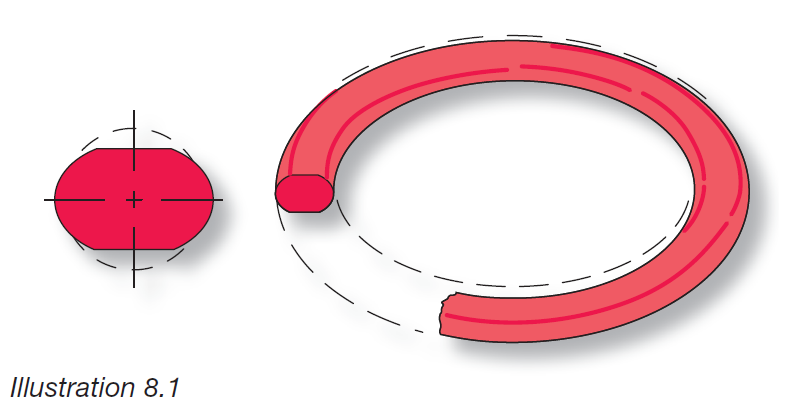
Failure Pattern: Common to both static and dynamic seals, compression set failure produces at surfaces on both sides of the O-ring’s cross section.
Problem Sources: Selection of elastomer with poor compression set properties... Low heat resistance of material... Excessive swelling of O-ring material in system uid... Too much squeeze to achieve seal... Incomplete curing (vulcanization) of O-ring material during production.
Suggested Solutions: Employ a low set elastomer... Specify an O-ring material that resists both operating and friction generated heat... Re-check O-ring material compatibility with system chemicals... Reduce O-ring squeeze if possible... Inspect incoming O-rings for correct physical properties.
Extrusion & Nibbling
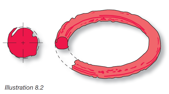
Extrusion & Nibbling Failure Pattern: Typical of high pressure systems, this pattern can be identi ed by the many small bites (nibbles) taken from the O-ring on the low pressure (downstream) side.
Problem Sources: Excessive clearances... Excessive system pressure...O-ring material too soft... Degradation of O-ring by system uid... Irregular clearance gaps caused by eccentricity... Improper machining of O-ring gland (sharp edges)...O-ring size too large for gland.
Suggested Solutions: Decrease gland clearances by machining... Use back-up rings to prevent extrusion... Use harder O-ring material... Re-check elastomer compatibility with system chemicals... Increase rigidity and improve concentricity of metal components... Break sharp edges of gland to a minimum radius of .005"... Install proper size O-ring... Consider a reinforced composite seal such as rubber-bonded-tometal.
Abrasion

Failure Pattern: Occurring primarily in dynamic seals involving reciprocating, oscillating, or rotary motion, this failure pattern can be identi ed by a attened surface on one side of the O-ring’s cross section.
Problem Sources: Metal surfaces too rough (acting as an abrasive)... Metal surfaces too smooth causing inadequate lubrication... Poor lubrication ... Excessive temperatures... System contaminated with abrasives.
Suggested Solutions: Use recommended metal nishes...Provide adequate lubrication (considerinternally-lubed O-rings)... Check material compatibility with system temperature... Eliminate abrasive contamination with lters and/or wiper seals ... Consider change to a more abrasive resistant O-ring material such as carboxilated nitrile or urethane (see Section 5, Material Selection Guide).
Heat Hardening & Oxidation
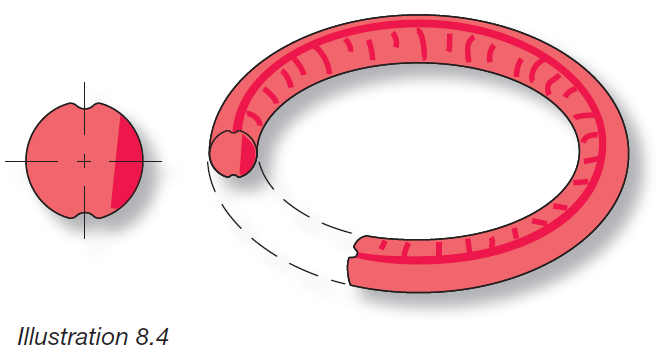
Failure Pattern: Seen in both static and dynamic seals, the surface of the O-ring appears pitted and / or cracked, often accompanied by the atness of high compression set.
Problem Sources: Excessive temperature causing elastomer hardening, evaporation of plasticizers and cracking from oxidation.
Suggested Solutions: Specify high temperature O-ring materials with antioxidants... Lower the operating temperature.
Installation Damage
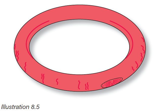
Failure Pattern: Occurring in both static and dynamic seals, this failure mode is marked by short cuts, notches, a skinned or peripherally peeled surface.
Problem Sources: Sharp edges on mating components of the O-ring gland... Sharp threads over which the O-ring must pass during assembly ... Insuf cient lead-in chamfer... Oversize O-ring ID on piston... Undersize O-ring ID on rod... Twisting or pinching of O-ring during installation... No O-ring lubrication during installation... Low tear resistant elastomers such as Silicone.
Suggested Solutions: Break all sharp edges... Cover threads with tubes or tape during O-ring installation... Provide a 15-20° lead-in chamfer... Install correctly sized O-rings and use lubrication during assembly.
Plasticizer Extraction
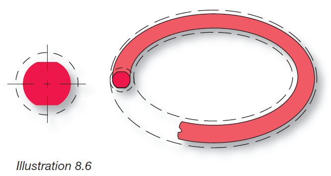
Failure Pattern: Occurring in both static and dynamic seals, primarily in fuel system service, this failure pattern is marked by loss of physical volume.
Problem Sources: Extraction of plasticizer by system chemicals.
Suggested Solutions: Employ a chemically compatible O-ring material.
Excessive Swell
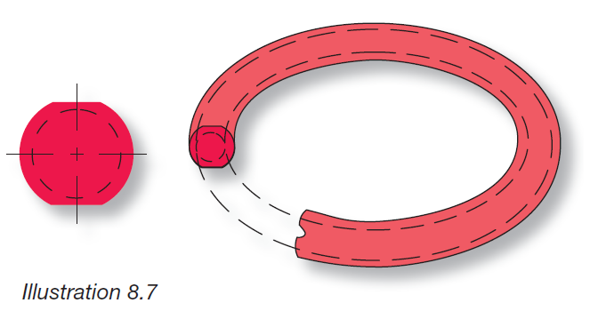
Failure Pattern: Easily identi ed by a marked increase in seal dimensions and occurring in both static and dynamic situations. Results in a reduction of physical properties and can result in improper sizing between seal and gland. Dynamic applications are especially prone in that friction accelerates seal failure.
Problem Sources: Like a sponge, the seal absorbs the surrounding uids and swells to the point of malfunction because of incompatibility between seal compound and system environment (i.e. chemical incompatibility, high humidity, etc.).
Suggested Solutions: Employ a chemically compatible O-ring material.
Spiral Failure
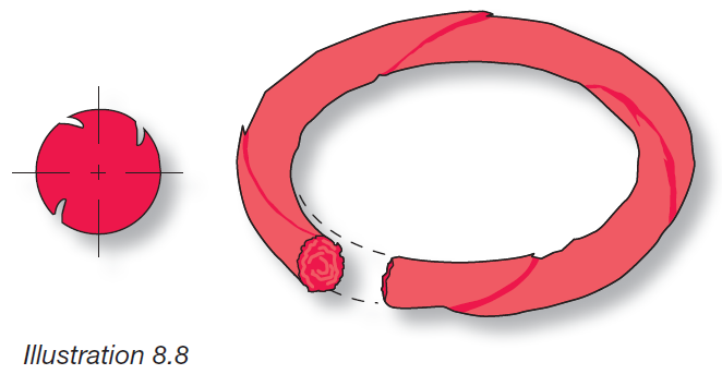
Failure Pattern: Generally found on long stroke, hydraulic piston seals, the surface of the O-ring exhibits a series of deep, spiral 45 degree angle cuts.
Problem Sources: Caused when some segments of the O-ring slide while other segments simultaneously roll. At a single point on its periphery, the O-ring gets caught on an eccentric component, or against the cylinder wall, causing twisting and development of 45 degree angle, surface cuts. Contributing Conditions Include: Eccentric components... Wide clearance combined with side loads... Uneven surface nishes... Inadequate lubrication... Excessive O-ring material softness... Too slow stroke speeds.
Suggested Solutions: Check for out-of-round cylinder bore... Decrease clearance gap... Machine metal surfaces to 10-20 micro-inch nish... Improve lubrication (consider internally-lubed O-rings)... Increase O-ring material hardness and/or cross section... Employ anti-extrusion back-up rings.
Weather or Ozone Cracking

Failure Pattern: Occurring in both static and dynamic seals exposed to atmospheres containing ozone and other air pollutants, this failure mode is marked by the appearance of many small surface cracks perpendicular to the direction of stress.
Problem Sources: Ozone attack of the polymer chains causing O-ring cracking.
Suggested Solutions: Employ O-ring elastomers that are resistant to ozone attack.
Failure Without Visible Evidence on Seal
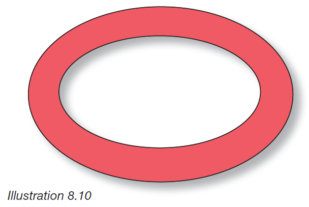
Failure Pattern: Of the various types of seal failure, this is among the hardest to diagnose because the result of the problem is not visible on the O-ring.
Problem Sources: Lack of compression... Tolerance stack-up...Eccentric components...Parting lines/ ash... Improper seal/gland volume relationship.
Suggested Solutions: Maintain recommended compression range for the application... Identify the amount of stretch as it reduces the O-ring cross section with increased stretch... Determine the component tolerance stack-up as it directly affects the seal cross section... Consider maximum component shift in design to ensure that compression is still contained within recommended compression range... Avoid parting lines in O-ring grooves as they tend to be areas of ash and mismatch... Ensure that the O-ring gland volume surpasses the O-ring volume to allow for seal expansion without seal detriment.
Explosive Decompression
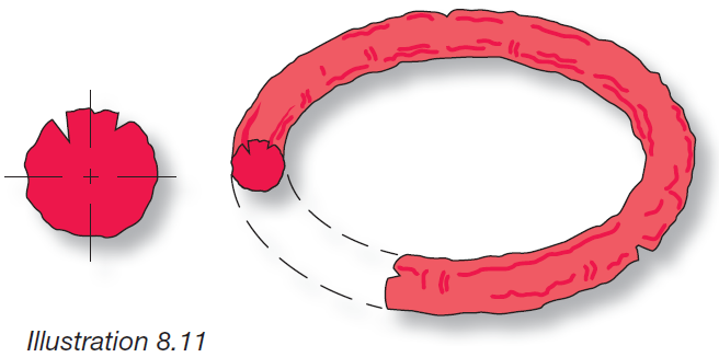
Failure Pattern: Marked by random short splits or ruptures going deep into the O-ring’s cross section. When the O-ring is rst removed, the surface may also be covered with small blisters.
Problem Sources: Absorption of gas by O-ring while operating in high pressure conditions. Subsequent rapid decrease in system pressure traps gas within the O-ring’s micropores, causing surface blisters and ruptures as the gas escapes.
Suggested Solutions: Increase time for decompression... Increase material hardness to 80-95 durometer range... Reduce O-ring cross sectional size... Specify a decompression resistant material, such as Nitrile.
